Verde Rebuild Week 4
Feb 11-12, 2006
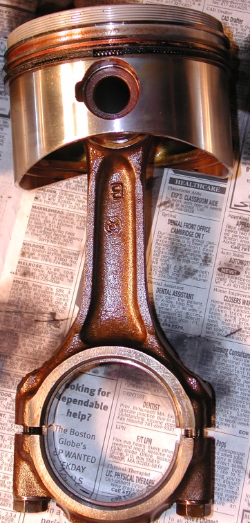
Make a lot of progress this weekend! Took out the rod bolts and pulled each of the pistons, none of the rings are broken and all seem to be in decent shape. Still no smoking gun... Will be replacing them anyway.
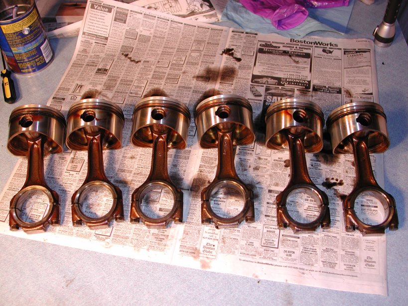
The pistons
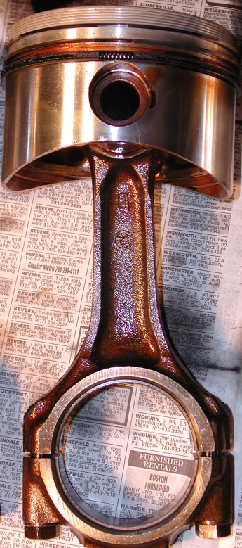
Some close ups of each piston with the rings rotated so all the gaps are showing:
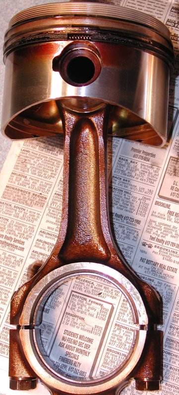
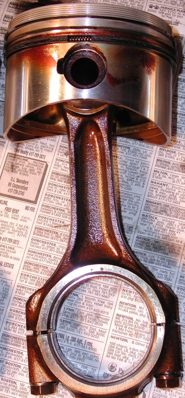
Pistons 1-2, 3
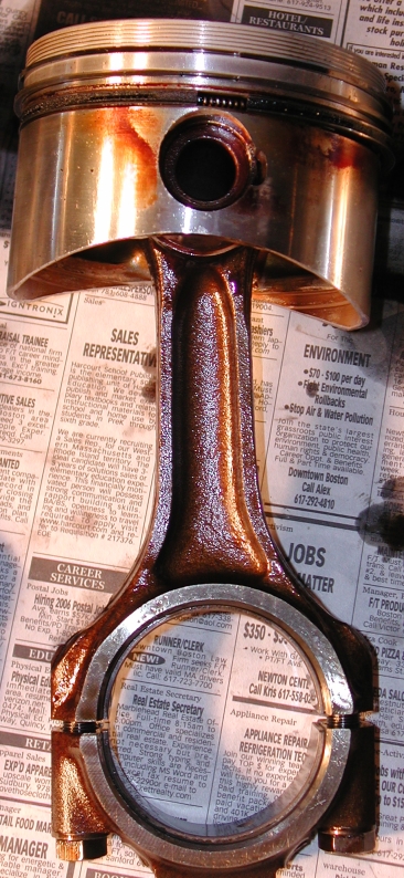
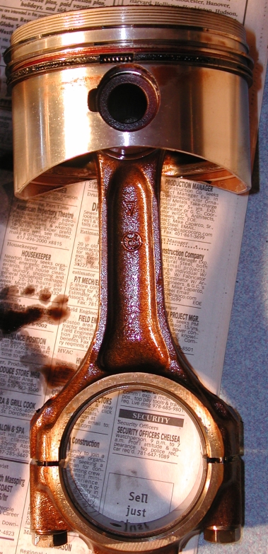
Pistons 4-5, 6
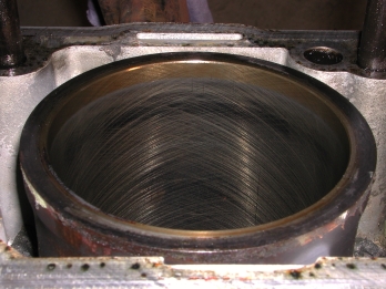
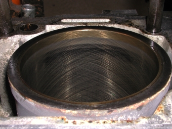
Here are the liners with the pistons removed, they are all stuck in there really well. I can't get them to budge, posted a query to the AlfaBB today asking for some hints on how to get them out. Got a couple responses to try using a rubber mallet and some hardwood (which I had already tried), turns out I was being a little too gentle... I guess normally you don't really have to remove the liners but to be safe I decided to replace ALL the seals in the engine so I'm going to pull them. In for a penny in for a pound.
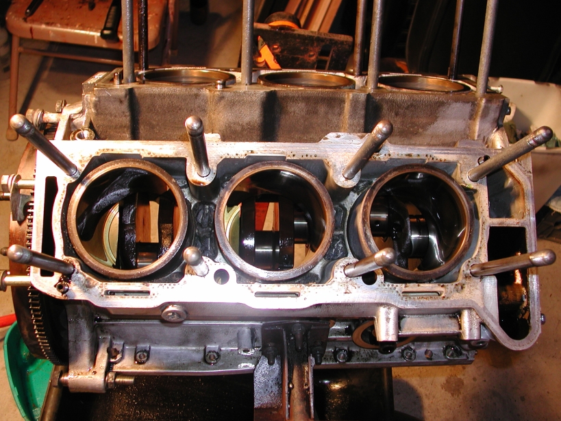
3-2-1 Side
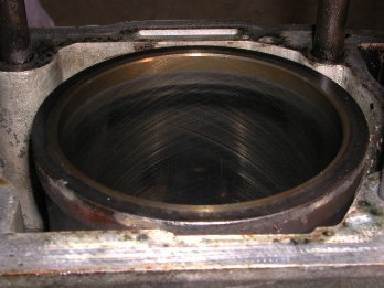
Liners 3-2, 1
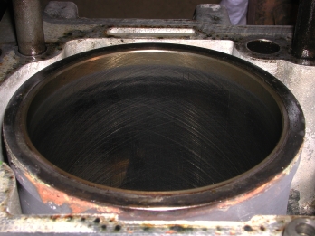
4-5-6 Side
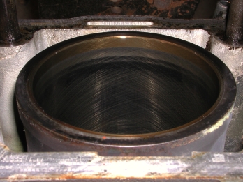
Liners 3-2, 1
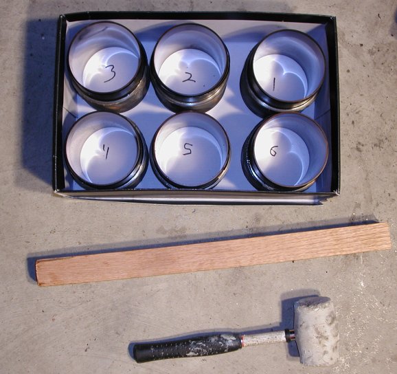
Here are the liners in a shoe box, ended up using a 1.5" x 1.5" piece of oak I had sitting around. I used the left hand side, you can see the corners rounded off as pieces of the wood split off during the hammer hits. I didn't hit very hard. Make sure to have something underneath to catch them! The first one I did came out easier than I expected after hitting it a little harder and I ended up catching it with my foot, close call! I put a box on a folding chair right under the block to catch the others. I also marked they cylinder number on the inside of each liner with a sharpie. NOTE: You can't really use this method effectively with the crank in there, not enough room so I actually did it after I removed the crank (below) but I put the pics up here so I can keep all the liner stuff together.
Liners after removal
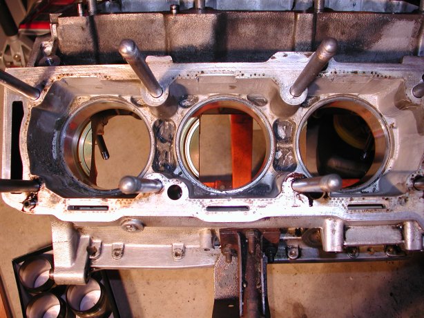
Block without the liners
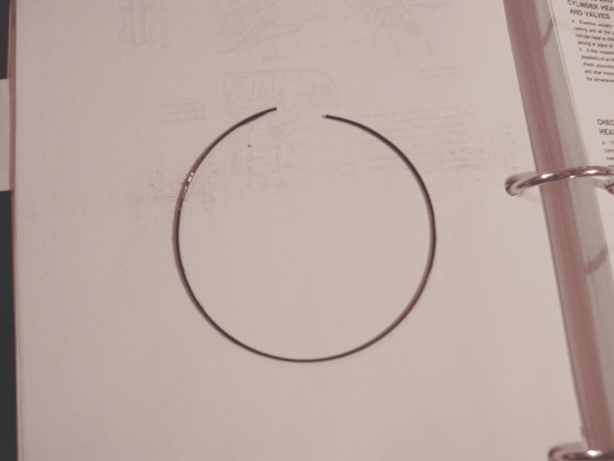
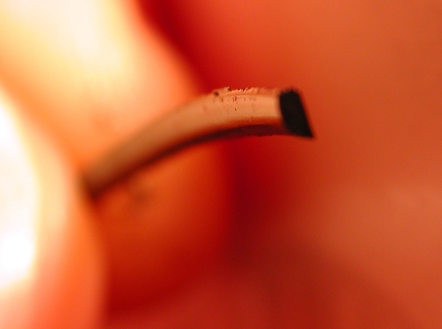
Three out of six of the liner "o-rings" were broken when I pulled the liners out. I'm guessing they broke when I pulled the liners as otherwise I would have had coolant in the sump of which there was none, just old and brittle I guess. Here's a pic of one of the broken o-rings, and another of the shape of it. I had been assuming these would just be big rubber one's but they seem to be made out of some kind of really thin plastic and are definitely not cylindrical now (if they ever were)!
OK, enough about the liners already! Next I needed to take the flywheel off so I fired up the compressor and got out my Husky (Home Depot) impact wrench and went at the flywheel bolts...nada...worked fine when I took the Spiders flywheel off a couple times but would not budge the Verde's. Dang, now what? I decided to try my 1/2" socket wrench and apply my 200 lbs of mass to it fand they budged, a few more hard pushes and they all came out. Piece of junk Husky! Picked that up quite a while ago when the kit it was in (along with air ratchet and some sockets) was on one of those yellow tag clearance sales for $25, now I know why :-). Make sure to mark the flywheel relative location on the crank spindle, I used some white touch up paint. To keep the flywheel from turning while heaving on the bolts I used the Volkswagen flywheel lock that I picked up for $8 a while back while doing work on the Spider, you can easily find these online, not a perfect fit but close enough to get the job done.
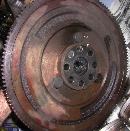
Mark the relative location of the flywheel on the crank so you can put it back
on the same way (see the white paint), also a pic of the flywheel lock tool
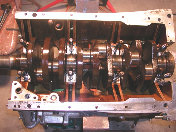
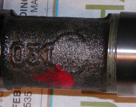
Now to get the crankshaft out...took some pictures so I can keep
track of the way the main caps are installed so they can go back in the exact
same way and place they came from! Notice the numbers on them.
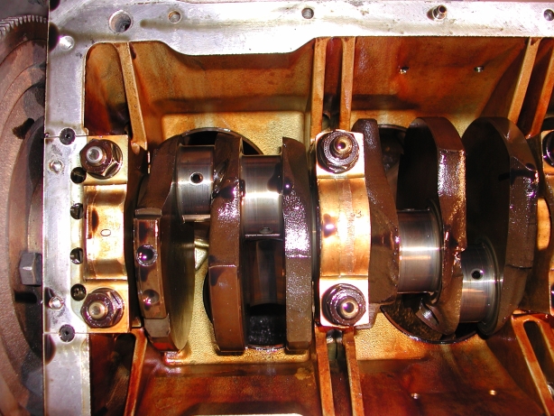
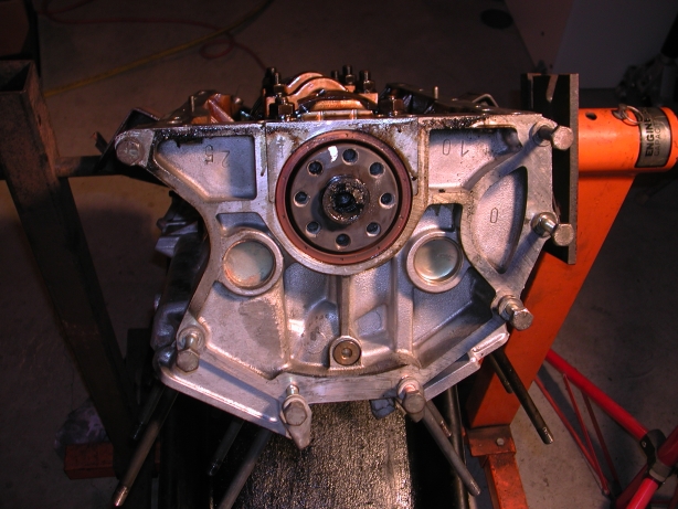
Once I got the nuts off the caps took a little side to side persuading with the rubber mallet to break the oil seal of the main bearings to the journals, the hardest one to get out was the flywheel end with the cigarette seals (#0) in the pic above. Couldn't knock that one side to side, just had to grab tight and pull up trying to rock side to side ever so slightly until it started moving. Here's the after shot:
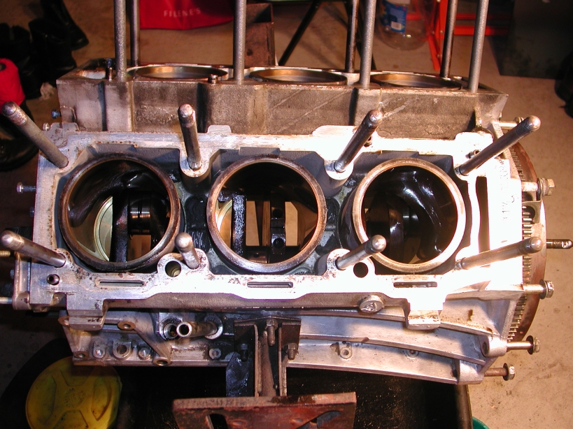
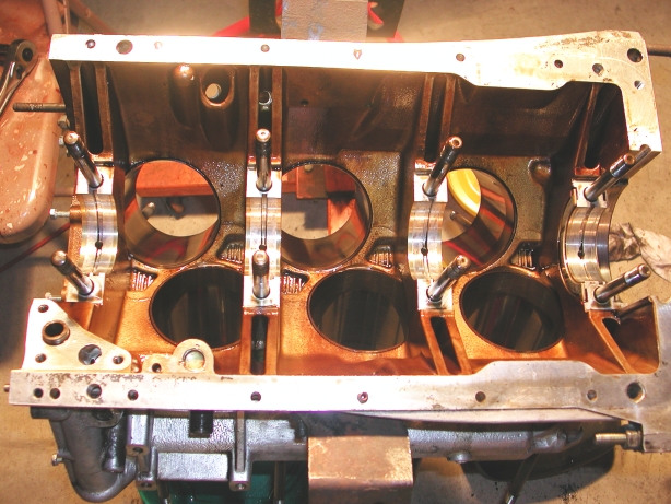
Here's a shot after the crank it out (man that thing is HEAVY!), you might notice that the liners are still in, well you caught me, I actually removed them after I removed the crank (see above in the lengthy liner section). You can see how there is a LOT more room to work with when the crank is out of the way.
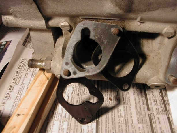
Decided to take the intake pipes off of the heads now, turns out one of them only had one of the two gaskets that were supposed to go on either side of what the shop manual calls the insulating gasket (the thick one).
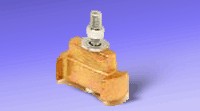
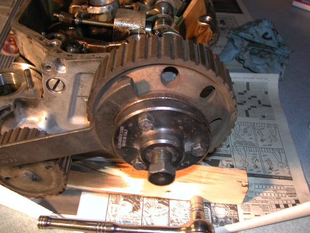
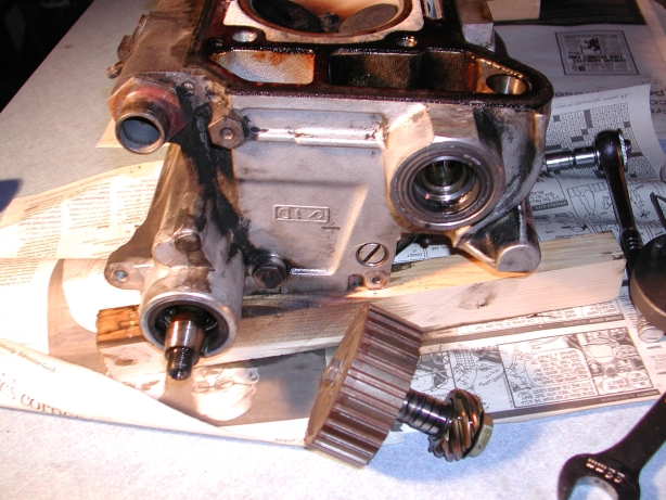
Now time to take the cam and distributor drive pulleys off. While you could do it without the special tools (A.2.0361 and A.3.0521) it sure makes the job a lot easier! You can buy the top one at some of the usual suppliers. I was able to borrow a big pile of the Alfa tools from a friend. You can probably just use a normal pulley puller but since I had the real one I gave it a try, they came off no problem! Here's a shot with both tools on (this is after the nut securing the pulley was removed of course).
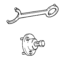
The distributor drive pulley is slightly different, you don't need the puller tool but you can use the wrench tool to hold it in place while you undo the outer nut. You also need to take the inner nut off but you need to unbend the washer first, this turned out to be quite a pain to do!
Here's the drive removed and the parts screwed back together:
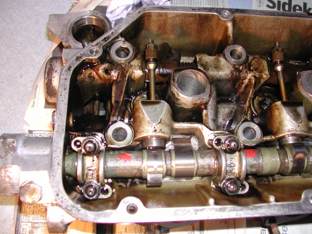
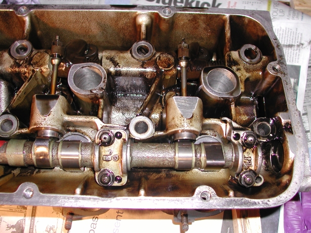
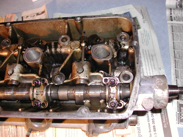
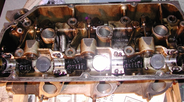
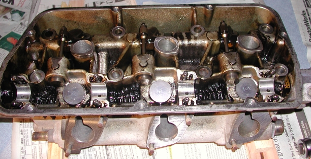
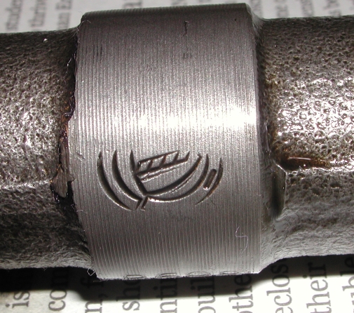
On to the cams...some more pics to keep things straight later, notice the #'s and arrows on the caps:
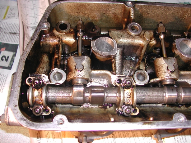
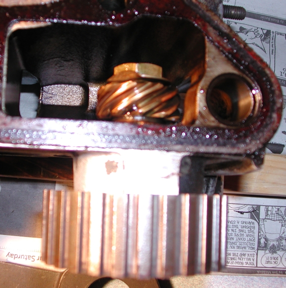
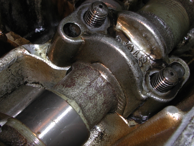
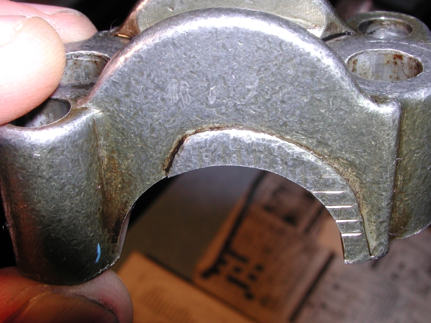
Looking a little closer at the caps I noticed some odd looking
machinings on one side of a few of the caps, I wonder if this is where those
metal shavings cam from? Hard to tell. A couple of the others looked
similar but the metal on those looked a little smoother while this one looked
more "sharp" making me think that this is at least a possibility for those shavings.
Update 11/16/12: As I'm changing the format of all the pages I'm looking back at the pictures for the
first time in a LONG time and it looks to me now that these metal bits are actually some stripped threads
from a threaded bolt hole rather than off one of the cam caps.
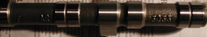
Here are the cams out:
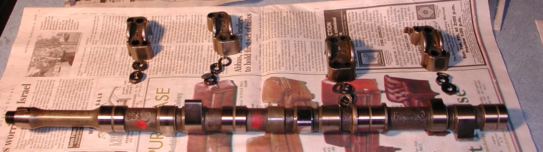
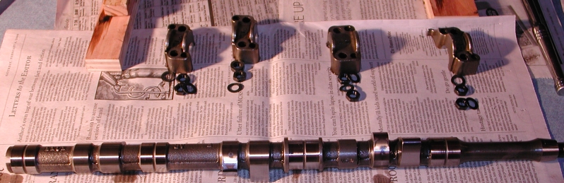
And some markings on the cams, I assume they are the stock cams:
Week 1: Jan 21, 2006 - Preparing to remove the engine
Week 2: Jan 28, 2006 - Getting the engine out of the car
Week 3: Feb 04, 2006 - Removal of the heads and oil pan
Week 4: Feb 11, 2006 - Removal of the pistons and crankshaft
Week 5: Feb 13, 2006 - Mar 26, 2006 - Much time passes with little rebuild progress...but got other stuff done
Finishing Up: Jul 02, 2006 - Much more time passes but finally finished!