Speedo Fix Using Dakota Digital SGI-5
May 4, 2014
I rebuilt and installed a Platinum tranny (4.10 limited slip) into the Verde last
summer. Doing so causes the speedometer to be off by 15% or so so I've been meaning
to install the Dakota Digital SGI-5 box that I bought a while ago to fix it but didn't
get around to it until today. The install is quite simple but can be a little confusing
which wires to hook up and which dip switch settings to set and questions about this get
asked on the AlfaBB fairly frequently so I figured I'd document what I did.
First you have to remove the rear seat bottom and you will find the Jaeger amplifier box
under it on the drivers side (US).
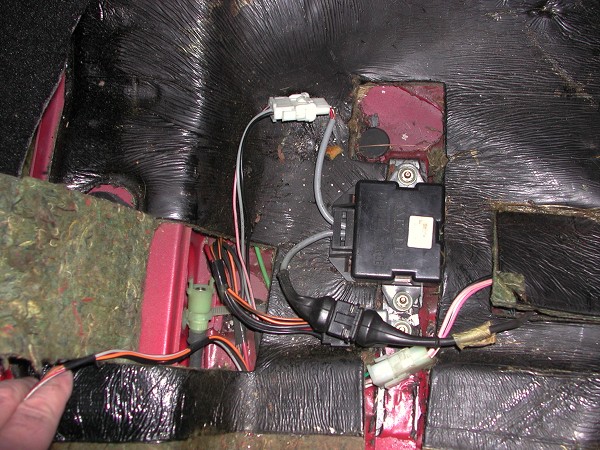
Original setup, I don't have ABS anymore hence the disconnected cable
Here is a close up of the connector coming out of the amplifier. The top goes to the amplifier, the bottom goes to the speedometer. The red and pink wires are switched 12v, the white and gray wires are the speed signal, and the copper and black wires are ground.
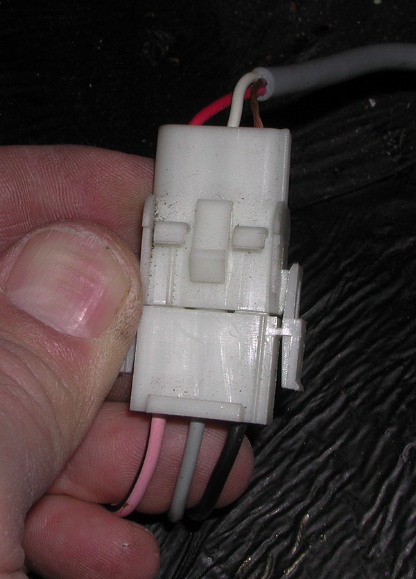
Connector for the wiring from the amplifier to the speedometer
I didn't want to cut any of the original wires so I cut some connectors off
of an old Milano wiring harness I had lying around from a car I parted out.
If you don't have these lying around you'll either have to cut wires to splice
the Dakota Digital in or find someone who is willing to part with the connectors.
I cut the connectors off with about 8-10 inches of wire pigtails on them.
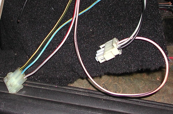
Pigtails cut from and old Milano wiring harness
Here is the SGI-5 box, you can see what connections I use for it.
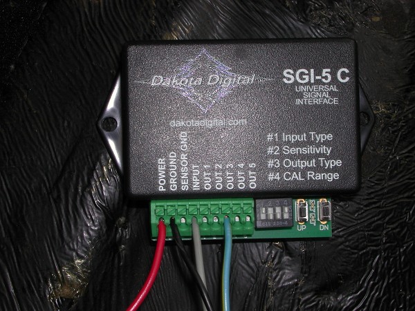
Dakota Digital SGI-5 Box
Here is a wiring diagram of the connections. For the power connection I twisted the two power wires from the pigtails together and put them in a single spade connector then took another piece of red wire and put the other connector on that and then finally plugged the other stripped end into the SGI-5. I did the same thing for the ground wires.
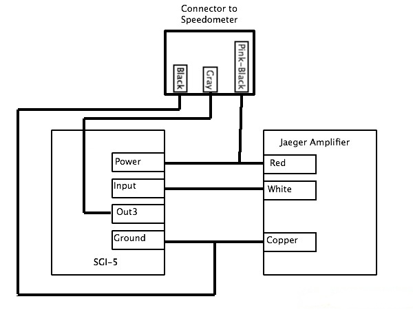
Wiring Diagram
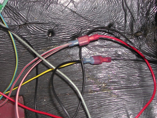
Closeup of the 2 into 1 wires for power and ground
Finally I set the dip switches to 1-on, 2-off, 3-off, 4-on as can be seen
in the picture above. You should be all set now and just get a GPS to tell
you your speed and someone to hit the up/down switches to properly calibrate
the unit while you are driving. Once I was happy with that I secured it
with a self tapping screw.
Here is a shot of it all wired up.
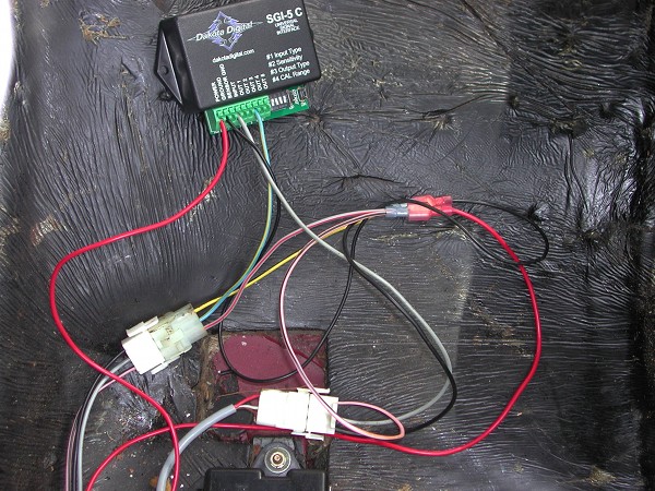
All wired up and ready for a test/calibration drive